Piedroit: A Raspberry Pi-powered USB Footpedal (Part 2)
Posted by Dylan Beattie on 18 May 2020 • permalinkIn part 1 of this post, I described the software and config required to use a Raspberry Pi Zero W to create a bank of footswitches that the host computer thinks is a USB keyboard. So far, so good: a little Python hacking, some Linux modules, a bit of GPIO and USB HID programming. All nice and friendly and revision-controlled.
That’s only half the problem, though. The main reason I’m building this thing is that I want a way to control the computer by stamping on things. When I’m playing the guitar and doing live shows, on stage or streaming via Twitch or YouTube, I want to be able to switch shots and control backing tracks by pressing switches with my feet. Now, I’m not exactly sure what would happen if 102kg of slightly excitable developer stood on a Raspberry Pi Zero W – or a normal computer keyboard, for that matter – but I suspect if it happened regularly, the devices in question might start complaining a bit.
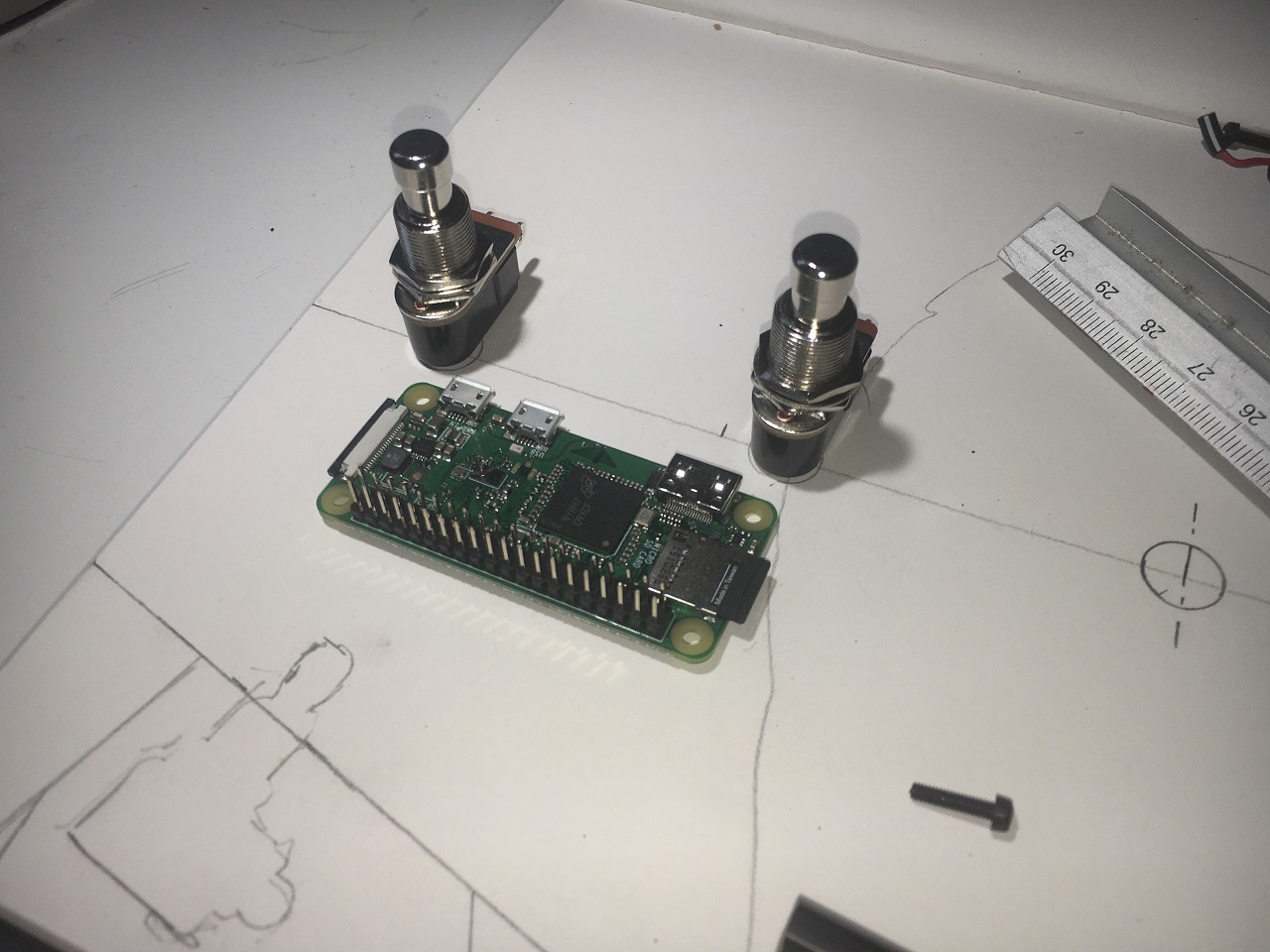
So having solved the logical elements of this puzzle, let’s figure out the physical bits. How do you connect a Pi Zero to a bank of footswitches that can cope with a big hairy guy pressing them with a pair of size 10 boots?
Well, as with many problems in life, the answer is… metal. In this case, 0.6mm bright mild steel sheet, because that’s what I could get hold of. I don’t have access to a proper machine shop or any welding gear (#lifegoals), so I had to come up with a design that I could make using the tools and materials I had available, but which would protect the Pi and other bits of delicate circuitry within.
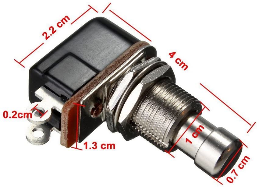
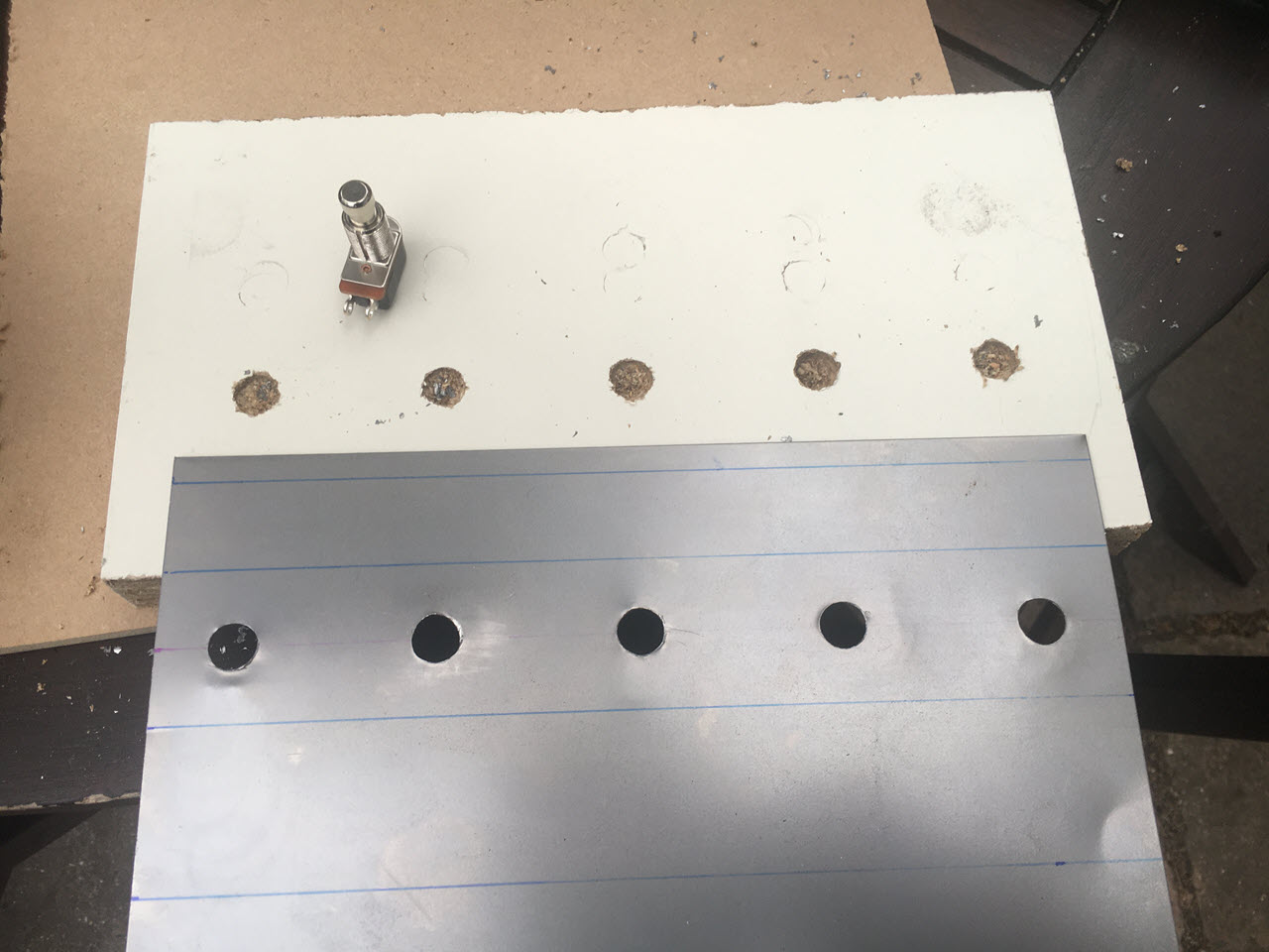
The switches I’m using for this project are a brand called Mintice, available from Amazon for £11.79 for a pack of 5. They’re pretty easy to work with, other than requiring you to drill a 12mm diameter hole… making holes in sheet steel is easy, especially if you have a drill press… I don’t have a drill press. I’m working with a cordless hand drill here, so making sure the holes end up exactly where they’re supposed to be is a bit tricky.
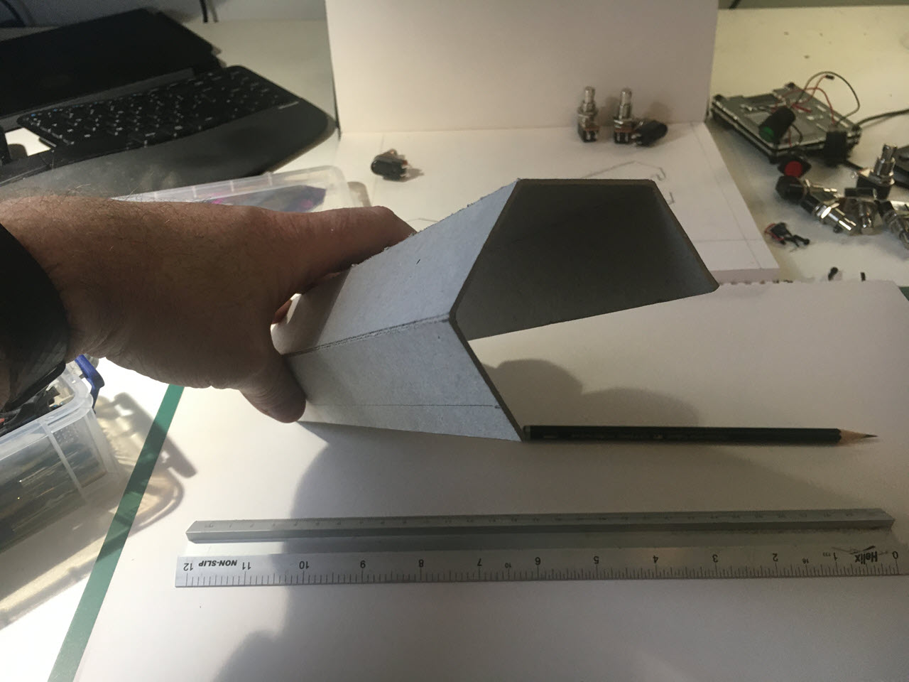
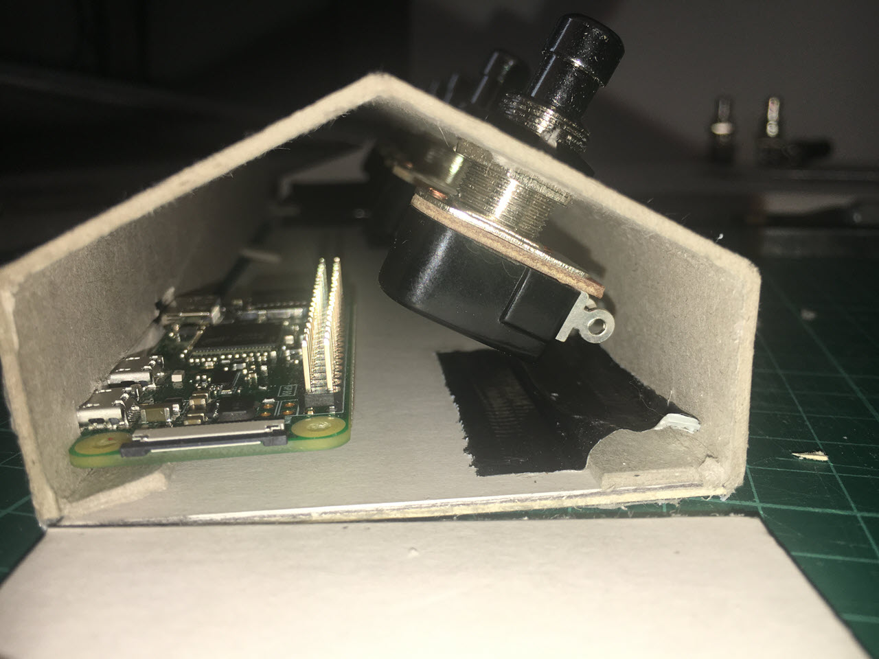
The Cardboard Prototype
Just like software, you should always plan to build one version to throw away. Unlike in software, when it comes to metalwork it’s normally really obvious which one’s the prototype… it’s the one made out of JavaScript cardboard. The prototype I’m building here is to answer a couple of key questions:
- Will all the components actually fit?
- How much sheet stock will I need, and what shapes will I need to cut?
- Is there enough space between the switches that I won’t accidentally press two switches at once?
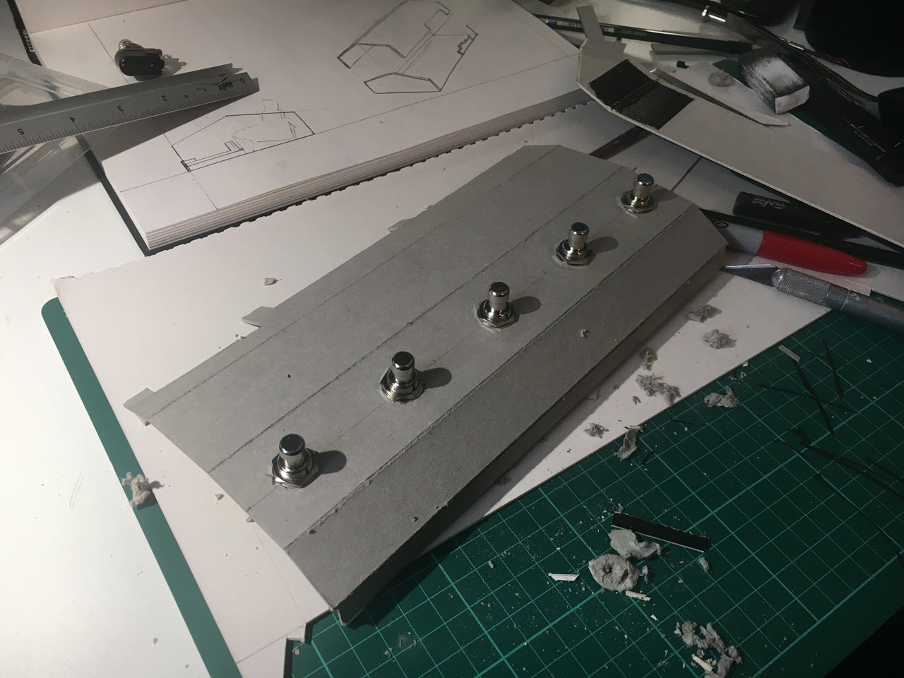
Time to Get Metal
The cardboard prototype worked. The components all fit, nothing’s fouling anything else, and it’s small enough to make from a single sheet of the 250mm x 400mm steel sheet stock I had available, but big enough to install five switches on the unit with enough distance between them that I’m not going to hit two switches at once.
Now I just need to make the same thing again, except in steel instead of cardboard. That’s not actually as daunting as it sounds. I really enjoy working with steel. Cardboard’s easy to cut and fold, sure, but it also frays and has a tendency to unfold. Steel takes time (and the proper tools) to cut and shape, but once you fold it, it stays folded.
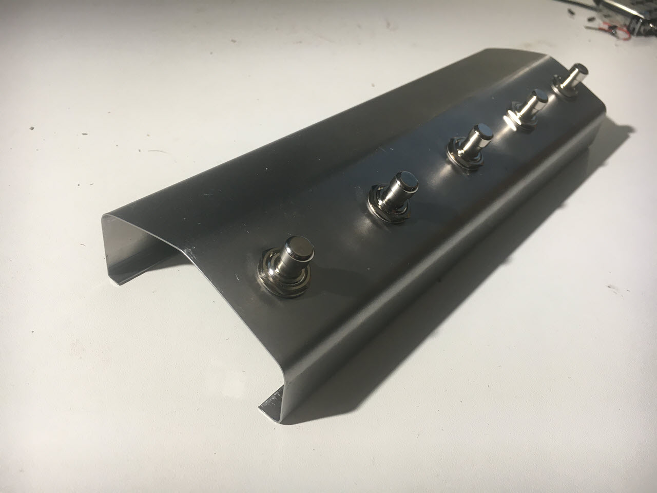
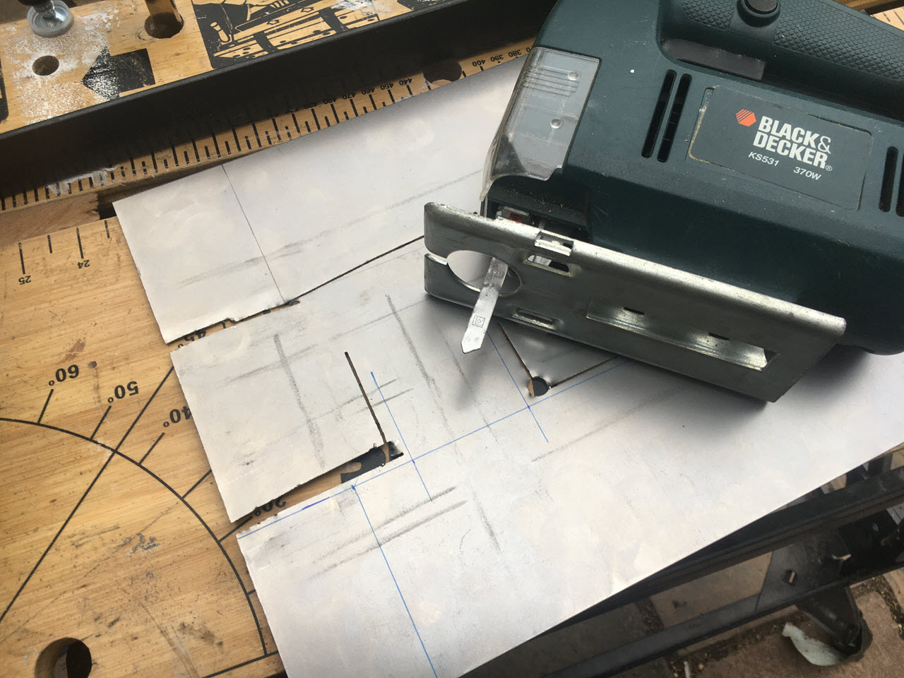
First step was to cut a piece of steel for the top of the housing, and then drill the five mounting holes for the switches:
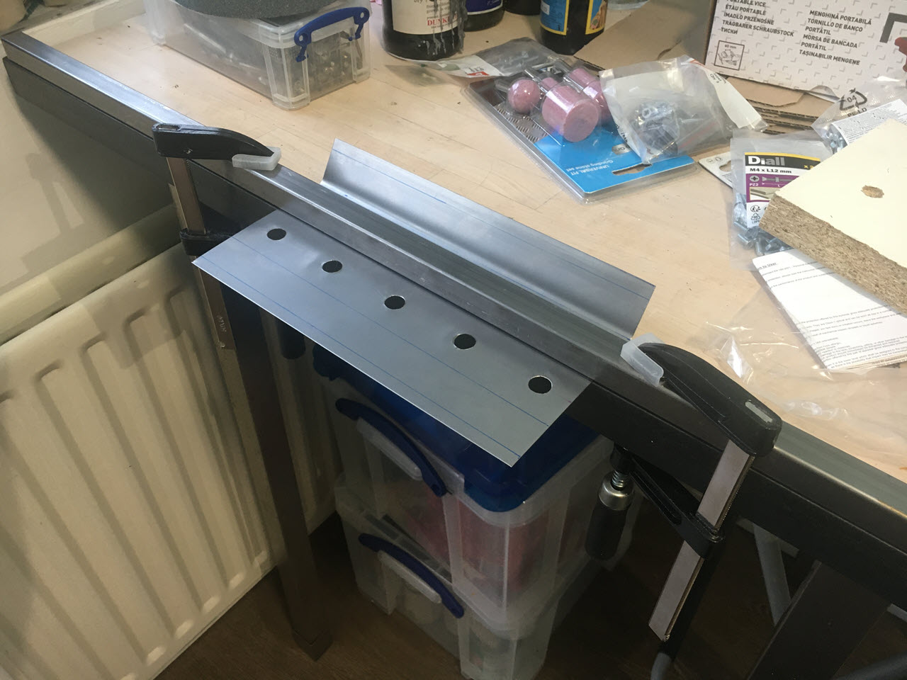
Next step was to bend the top part of the housing. There’s dozens of videos on YouTube about how to bend sheet metal – some show you how to use a machine called a metal brake; some show you how to make a metal brake if you don’t have one available, and some show you how to bend metal without a brake. This video from Cosador is great if you want an overview of a few different techniques. I ended up using hand bends and hammered bends for most of my project, using a couple of lengths of cold-rolled steel angle and lots of clamps to hold everything straight. It came out OK – not perfect, but good enough for what I need.
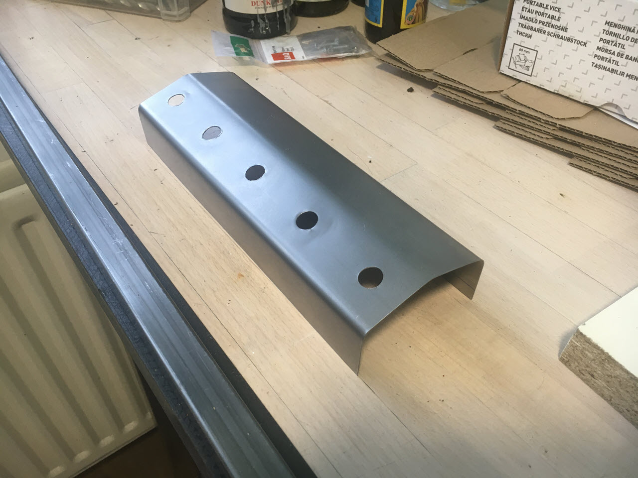
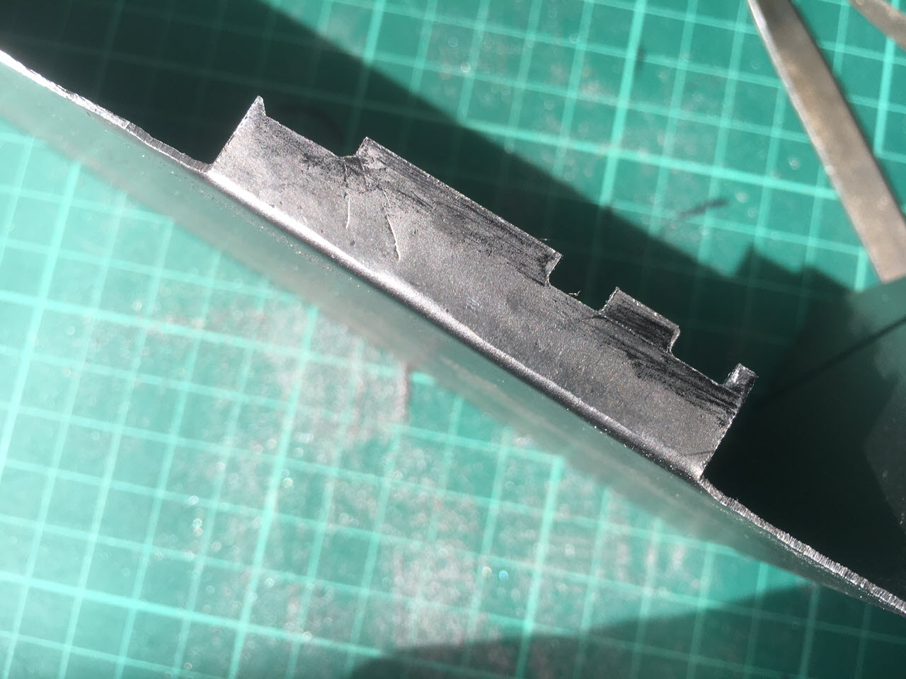
For the bottom half of the casing, I needed to bend up the edges of the case, but also to cut notches for the HDMI and USB ports on the Pi Zero.
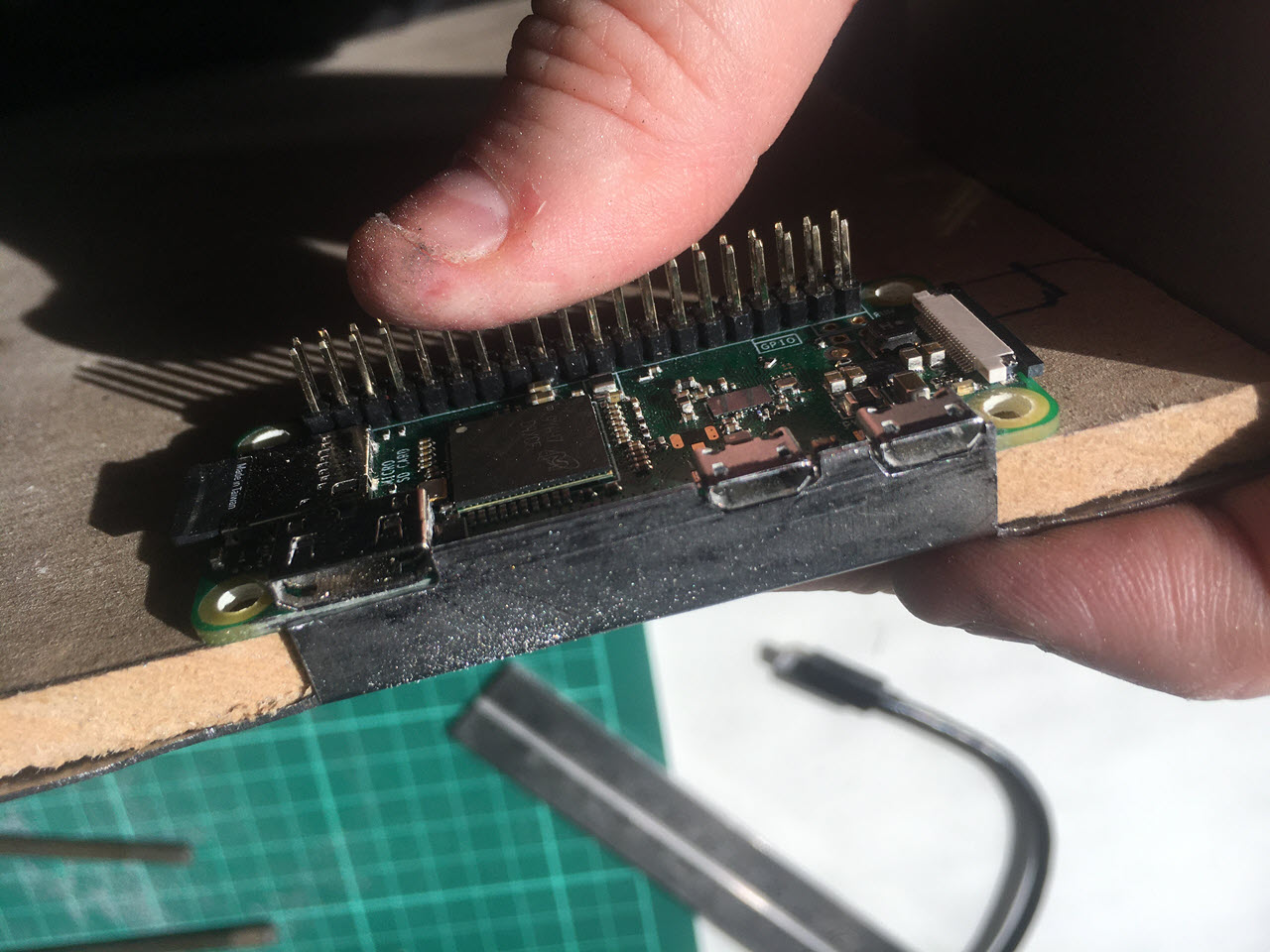
The Pi board itself was mounted on a small piece of 6mm MDF – you can see the original sheet in this photo, that I’m using to hold the Pi in place to check the fit of the IO ports.
One more thing I did was to use a needle file to enlarge the mounting holes on the Pi so I could use 3mm screws. Out of the box, the Pi uses 2.5mm mounting screws. I don’t have any of those lying around – but I have lots of 3mm screws and bolts, so slightly enlarging the holes gave me way more options when it came to mounting the board.
Wiring it up
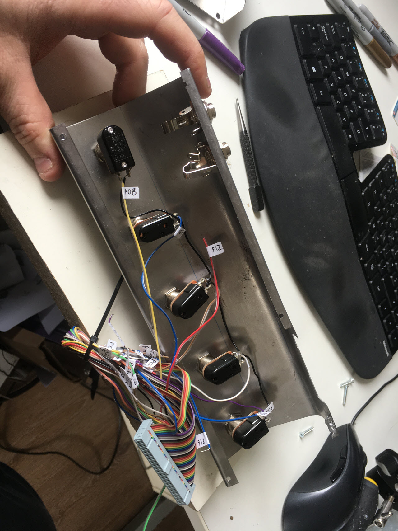
To wire the switches to the Pi’s GPIO ports, I cut one end off a 40-pin ribbon cable, giving me a wiring harness with about 15cm of wire on each pin. The fun part here was figuring out which wire connects to which pin. I used a Raspberry Pi breakout board for this part, and it took about an hour of testing connections with a multimeter and labelling each wire as I identified which pin it connected to. Fiddly, but not actually difficult.
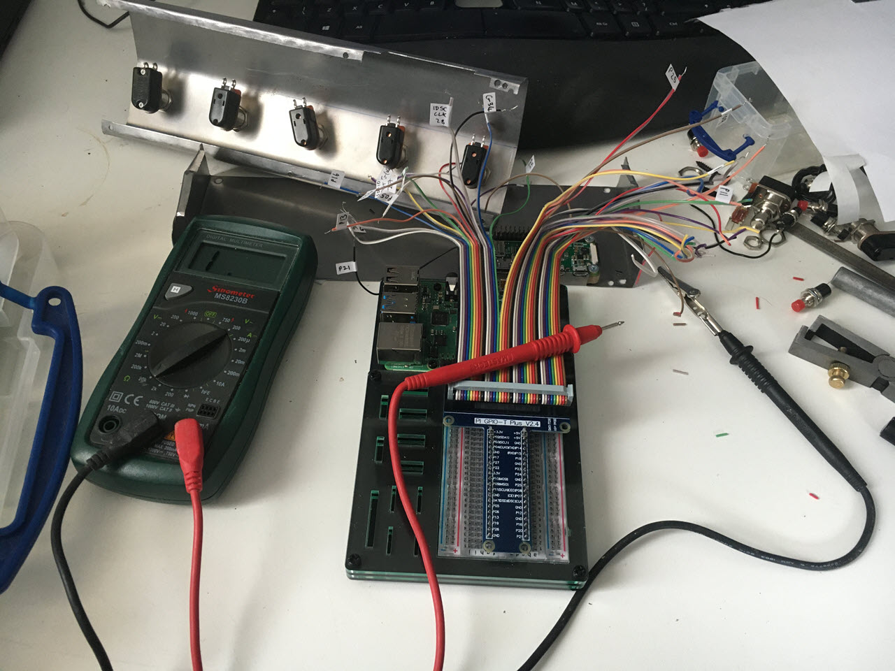
For this project, I wired GPIO pins 04-08 to switches 1-5. At this stage I also wired in two extra breakout ports – one’s a mono 6.5mm jack socket, the other is a stereo 6.5mm jack socket. I wired these into GPIO pins 9 and 10+11, so I could hook up three extra external footswitches to give me another three inputs on the board.
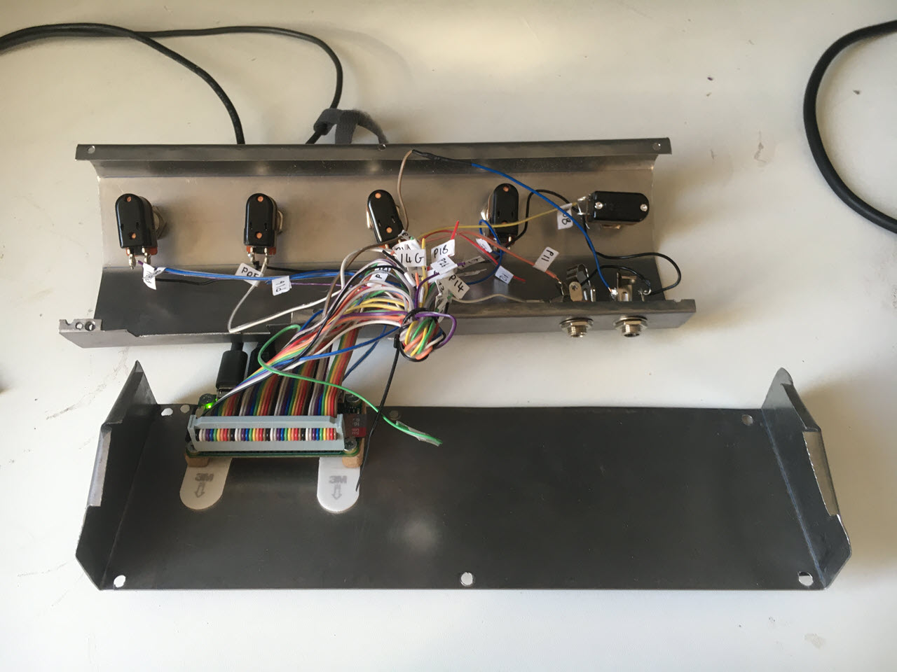
Here’s both parts of the casing, with all five switches and the two 6.5mm breakout ports all wired in and the ribbon cable seated on the Pi’s GPIO connector. You can see the 6 holes I drilled in the case here – the original plan was to tap M3 threads into the top half of the casing and assemble the case using M3 bolts. Turns out 0.6mm mild steel isn’t actually hard enough to hold a thread… two of them came out OK, one of them I stripped completely and ended up bodging by supergluing a nut in place above the hole, the other three I’m just going to ignore for now. You can also see the Pi board here mounted on a piece of 6mm MDF, which is attached to the steel using 3M Command Strips – again, that’s what I had easily to hand. They’re normally used to hold pictures on the wall, but they adhere to steel and to MDF pretty well and they’re easily removable if necessary.
And – that’s it! Put the whole thing together, boot it up, and… it works. Windows detects each footswitch as a key on a USB keyboard, and now I can control WinAmp, OBS, and any other application that supports global hotkeys by pressing footswitches.
Ideas for vNext
This was a great project. Frustrating in places, especially the Bluetooth dead end, but I had a lot of fun putting it together. At a time when so much of what we’re all doing – work, social life, entertainment – is all taking place on screen, it’s also a nice change to build something physical; something you can actually pick up and touch and handle.
But, of course, I have loads of ideas for building a better version.
-
The circuitry. The Pi is a great little computer, but… do I really need 512Mb of RAM in a footswitch? I’m also still keen to see what I can do with Bluetooth, so I suspect the next incarnation of the project will use either something like an Arduino or a Teensy, or I’ll cannibalise a Bluetooth keyboard and hack the circuitry from that into a footpedal controller.
-
Status LEDs. There’s currently no way of telling whether the board has actually booted up properly. It wouldn’t be that hard to wire up a couple of LEDs to the GPIO pins – something as simple as a red LED for power and a green LED that lights up once the USB keyboard event loop is running would make the device a lot friendlier.
And, of course, there’s all the “it would be cool if…” – reprogramming key mappings, macros, modifier keys… once you get into these kinds of projects, the hardest part is knowing when to stop.
But this one is done. I’ll be using it for a bunch of events I’m doing this week, including HalfStack Online on Friday, and I’m sure you’ll be able to catch it in action on a YouTube or Twitch stream near you before too long!