Piedroit: A Raspberry Pi-powered USB Footpedal (Part 1)
Posted by Dylan Beattie on 17 May 2020 • permalinkI often find myself doing daft things with computers and playing the guitar at the same time. I use laptops on stage to run videos and backing tracks, I record my own music, and, most recently, I’ve been livestreaming music over YouTube and Twitch for some of the online conferences I’ve spoken at.
Since playing the guitar tends to require both hands, many guitar amps and effects include some kind of footswitch controller, so you can switch between different sounds and effects without taking your hands off the guitar. For a while, I’ve been after something similar that’ll let me control a computer remotely using foot switches. I’ve used various kinds of foot controllers in the past, but none of them has ever done quite what I wanted. The two that have stuck around the longest are the AirTurn PEDPro and the iRig Blueboard.
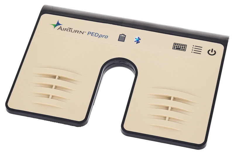
The PEDPro runs on Bluetooth and works great as a hands-free Powerpoint clicker. It connects to Windows or macOS as a Bluetooth keyboard, but it only has two keys, which are (normally) hardwired to be Left and Right. This works great for controlling Powerpoint, but it’s a bit limited.
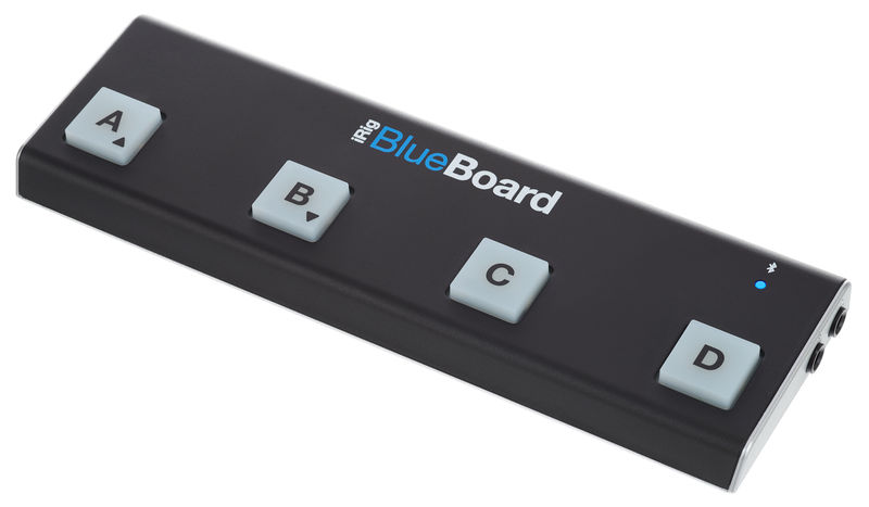
The iRig Blueboard has four footswitches, and works very nicely with iOS and macOS, but it connects to the host system as some kind of proprietary Bluetooth MIDI device, and it doesn’t work on Windows.
So I figured building my own pedalboard might be a fun lockdown project. At a bare minimum, I wanted to be able to switch between scenes in OBS and control some sort of media player at the same time, so I can stop/start videos and backing tracks and switch between different camera angles when doing live streams.
There’s two approaches I could have taken:
- Network-based: the footswitch device connects to wifi and sends signals to a host PC over the network. I write some bespoke software that runs on the host PC, which either translates those signals into emulated keystrokes, or controls the target applications directly.
- Device emulation: the footswitch connects directly to the host PC, via USB or Bluetooth, and shows up as a keyboard, joystick or some other kind of human interface device (HID).
I went for device emulation, mainly because the host PC is already going to be pretty busy handling multiple cameras, OBS, media playback, greenscreen effects, and live network streaming, and having my footswitch just show up as a keyboard seemed a lot more straightforward. Plus, I’ve done a whole bunch of network programming and client/server stuff, but I’ve never built something that emulated a physical keyboard before and it sounded like fun.
The Raspberry Pi Zero W
For this version of the project, I used the Raspberry Pi Zero W. Lots of people asked why I didn’t use an Arduino or some other device: well, I used a Pi because I like them. They’re wonderful little devices, they’re lots of fun to work with, and I’ve done some interesting projects with them before so I’m not starting from scratch here.
One very interesting idea which I’ll probably return to in a future project would be to cannibalise the controller from a Bluetooth keyboard and use that instead of building my own device. More on that in a moment.
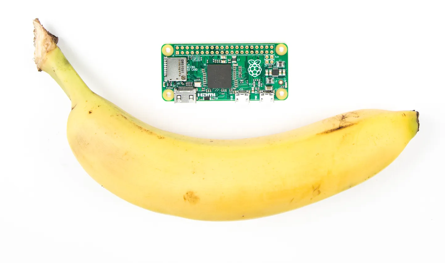
The Pi Zero is a tiny Linux computer, not much bigger than a stick of gum. It’s got a 1GHz single-core CPU, 512Mb RAM, a mini HDMI port, two USB ports – one for power, one for peripherals. Most important of all for this project, it has a bank of general-purpose input/output (GPIO) pins that you can wire up to external switches, LEDs, sensors, all kinds of things, and then write some fairly simple code to interface with them. Which is brilliant if you want to connect a bunch of mechanical footswitches to a tiny Linux computer and don’t really know what you’re doing.
The other nice thing about the Pi Zero W is that it’s got exactly the same hardware and programming interface as its big brother, the Raspberry Pi 4 Model B – so if you get into serious code-wrangling, you can use the more powerful Pi 4B as your dev platform, get your code working, then pop the MicroSD card out, put it into the Pi Zero and boot the exact same code on the smaller device.
Plan A: Bluetooth
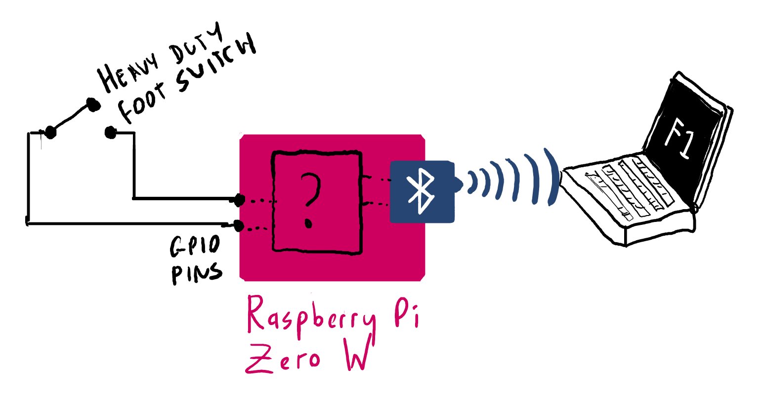
My first approach with this project was to get the Pi Zero to connect to the host PC over Bluetooth, and emulate a Bluetooth keyboard. I spent a rather fun, if occasionally frustrating, weekend playing around with this. You can read the tweet-by-tweet accounts from day 1 and day 2 – but to cut a long story short, I couldn’t get it to work well enough for what I wanted.
I got to the point where I could boot the Pi, start the various Python scripts, then go onto my Windows machine and add a new Bluetooth device – and it worked. The device would show up as paired, then connected, and it would actually send keystrokes to the host PC:
I have hardware switches connected to the Pi Zero GPIO pins. Pressing a switch sends a a keystroke to the Windows PC. The PC thinks it’s talking to a Bluetooth keyboard. The whole thing is as hacky as all hell - but it works. :) pic.twitter.com/VQp5jHjG8a
— Dylan Beattie 🇪🇺 @ 🏡🔑🔽 (@dylanbeattie) May 3, 2020
There was a problem, though. When I stopped the Python script that was running the Bluetooth service on the Pi, the device would go from connected to paired – and I could not find any way to get it to reconnect without removing and re-adding it. Which made the whole thing a bit impractical, particularly if I was going to try using it in any kind of live performance situation.
Any folks out there who know the intimate details of the bluez Bluetooth stack? I need to force a Linux device to connect to a host that’s already paired... you can see exactly what I mean in the video here. Any help much, much appreciated. pic.twitter.com/7YOYV59NfE
— Dylan Beattie 🇪🇺 @ 🏡🔑🔽 (@dylanbeattie) May 9, 2020
In this video, you can see that with my Logitech K380 Bluetooth keyboard, this works perfectly – and part of me wishes I’d just cannibalised a K380, taken out the controller chips and switches, and wired my own footswitches into it. That would have made the hardware side of this a lot more straightforward… but hey, we live and learn, right?
Plan B: Wired USB
In tech projects, it’s way too easy to get fixated on your current approach and lose sight of what you’re actually trying to accomplish. It was this tweet from Jonty – and particularly the phrase “you’re wayyyy down this rabbit hole” – that got me to take a metaphorical step back and remember that Bluetooth is not actually a requirement here. The goal is to be able to control OBS and WinAmp, on a desktop PC, using my feet. I’m trying to control a stationary computer from a stationary footswitch, so having a wire connecting the two is not a problem. It turns out the Pi Zero will also quite happily emulate any number of USB gadgets, from virtual keyboards to joysticks and network interfaces.
So, I recast the project a bit. The milestone for this part was to get to a point where:
- The Pi Zero is connected to a Windows 10 PC via USB
- The Windows PC thinks the Pi Zero is a keyboard
- I can run some Python code on the Pi Zero to send arbitrary keystrokes (including modifier keys) to the PC
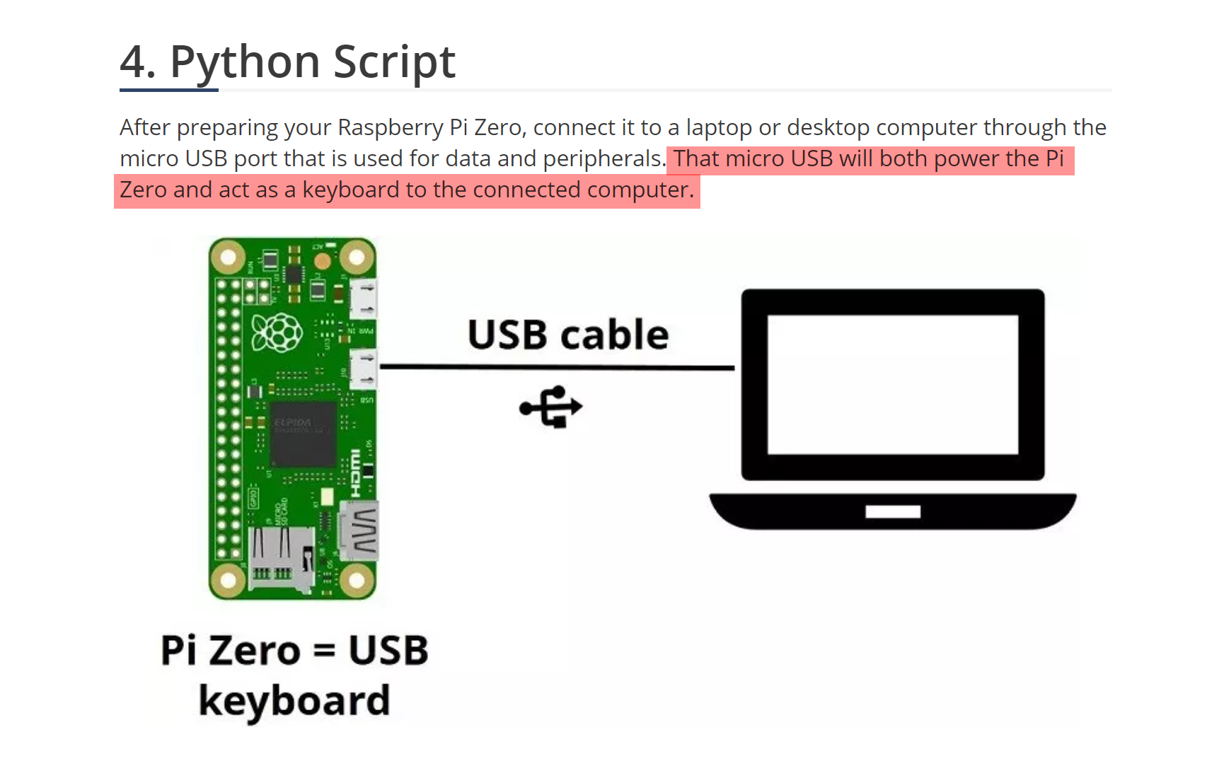
This was actually pretty straightforward, thanks to a really great article “Composite USB Gadgets on the Raspberry Pi Zero” over at iSticktoit.net. I did have one slight stumbling block: when I first started working on this, I originally found this tutorial instead. That’s almost exactly the same (the code samples are identical) except the Random Nerd Tutorials article says quite clearly that you can run the whole thing off a single micro USB port:
Now, a little later in the article, our Random Nerd author does actually say:
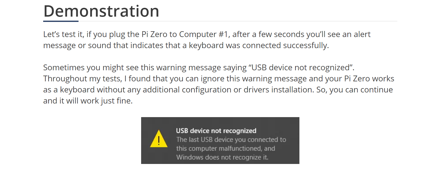
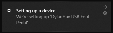
To say this does not match my own experience would be putting it mildly. The first few times I tried booting the Pi drawing power through this USB port, it caused all sorts of chaos, including completely shutting down the entire USB bus on my Windows PC more than once, leaving me with no mouse and no keyboard. That was fun. It is possible – I got a working setup a few times using only a single USB cable – but I wouldn’t recommend it. After a few rounds of this, I tried booting the Pi using standalone USB power, waiting until it was up and running, and then connecting the second USB port to the host PC – and it worked flawlessly. You have no idea how excited I got when I saw this little pop-up in the corner of my Windows 10 display:
TL;DR: Boot the Pi using dedicated USB power. Once it is up and running, connect the peripheral USB port to the host PC, and everything works fine.
The Code
The software side of this is really in two parts. First, there’s the configuration you’ll need to run to persuade the Pi to start pretending it’s a USB keyboard. Then there’s a bit of Python code that will detect when a circuit is closed across a pair of GPIO pins, and send a particular keystroke over the USB interface when this happens. This is wonderfully, beautifully simple on the Pi Zero, thanks to the RPi.GPIO library that makes it really easy to write Python code that talks to the GPIO pins. All the code for my implementation is available on Github, along with instructions about how to get it set up and running:
https://github.com/dylanbeattie/piedroit
The important part is here – piedroit.py. This is the code that detects events on the GPIO pins, translates them into the specific data structure required by the USB keyboard interface, and sends those events to the /dev/hidg0 device that’ll pass them to the host PC:
#!/usr/bin/env python
# piedroit: translate GPIO pin inputs into USB keystrokes
# https://github.com/dylanbeattie/piedroit

import RPi.GPIO as GPIO
import modifier_keys

NULL_CHAR = chr(0)

def send_data_to_usb(data):
  with open('/dev/hidg0', 'rb+') as fd:
    fd.write(data.encode())

def get_key_code(gpio_pin):
  # https://www.usb.org/sites/default/files/documents/hut1_12v2.pdf
  # Physical switches are wired to GPIO pins 4-11
  # I want footswitch #1 (GPIO pin 04) to send F1, #2 > GPIO02 > F2, etc.
  # F1 has USB key code 58 (0x3A), F2 is 59, etc.
  # So we can get the key code we need by adding 54 to the GPIO pin number.
  return(gpio_pin + 54)

def send_key_down(key_code):
  # USB key events are an 8-byte struct containing:
  # – a one-byte bitfield of modifier keys
  # – a null byte
  # – Up to six key codes. (USB allows you to press up to six keys simultaneously)
  #
  # This code will always send Ctrl+{key}
  modifiers = modifier_keys.LEFT_CTRL
  key_data = chr(modifiers) + NULL_CHAR + chr(key_code) + NULL_CHAR*5
  send_data_to_usb(key_data)

def release_all_keys():
  send_data_to_usb(NULL_CHAR*8)

def send_key_for_gpio_pin(gpio_pin):
  key_code = get_key_code(gpio_pin)
  send_key_down(key_code)

# This code will support GPIO pins 4-21, although
# only pins 4-11 are actually connected in my device
FIRST_GPIO_PIN = 4
FINAL_GPIO_PIN = 21
ALL_PINS = range(FIRST_GPIO_PIN,FINAL_GPIO_PIN)

# Tell the Pi which numbering mode we're using to talk to the GPIO pins
# https://raspberrypi.stackexchange.com/questions/12966/what-is-the-difference-between-board-and-bcm-for-gpio-pin-numbering
GPIO.setmode(GPIO.BCM)

for pin in ALL_PINS:
  GPIO.setup(pin, GPIO.IN, pull_up_down=GPIO.PUD_UP)

# Remember closing a switch connects the GPIO pin to ground (GND)
# so GPIO.input(pin) will return 0 ("grounded") or 1 ("not grounded")
SWITCH_CLOSED = 0

# Now we just sit in an infinite loop, reading all the GPIO pin states
# every time we loop, and watching to see if any pin state has changed.
previous_states = [1] * FINAL_GPIO_PIN

while True:
  for pin in ALL_PINS:
    state = GPIO.input(pin)
    previous_state = previous_states[pin]
    if (state != previous_state):
      if (state == SWITCH_CLOSED):
        print("GPIO PIN {} now CLOSED".format(pin))
        send_key_for_gpio_pin(pin)
      else:
        print("GPIO PIN {} now OPEN".format(pin))
        release_all_keys()

      previous_states[pin] = state

# This is good practice, but since we're going to sit in our loop
# until we kill the process or disconnect the power, we'll never
# actually get here. But in this scenario, that's OK.
for pin in ALL_PINS:
  GPIO.cleanup(pin)
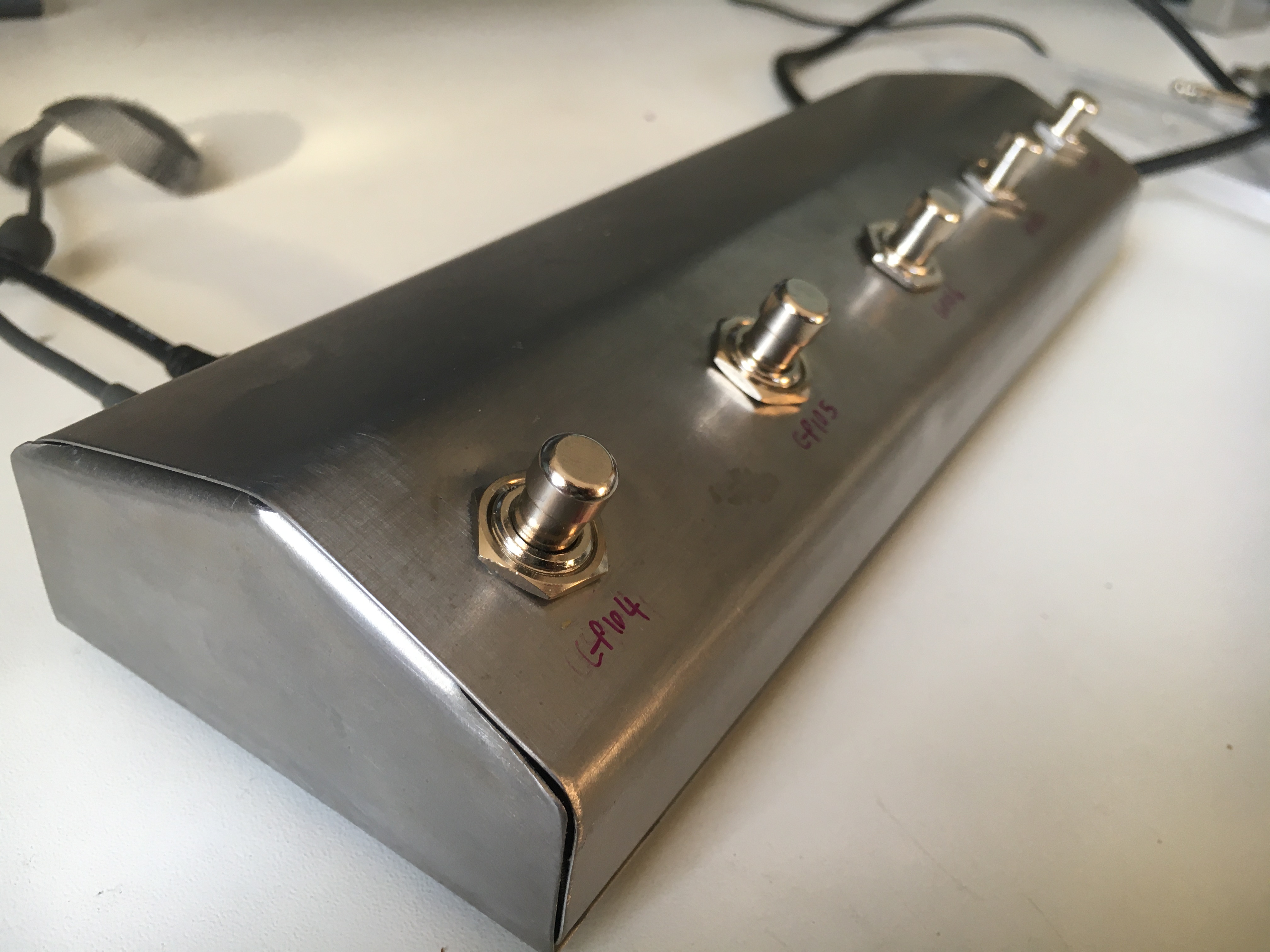
The Case
Finally, I needed a box to put it all in – a box that wouldn’t get upset if 102kg of Dylan stood on it wearing cowboy boots. Check out part 2 of this post which involves a lot less code – and a lot more sheet steel.
🤘🏻